The UPVC
sliding door is simply a sliding door made of steel added inside the UPVC
profiles. Specifically, UPVC is added with a certain proportion of stabilizers,
colorants, fillers, ultraviolet absorbers, etc., and is extruded into a molding
material, and then made into a door and window frame fan by cutting, welding or
screwing, and is equipped with a sealing strip. , tops, hardware, etc., at the
same time to enhance the rigidity of the profile, the steel lining (reinforced
ribs) need to be filled in the cavity of the profile beyond a certain length,
so that the sliding door is called a plastic steel sliding door.
Upvc Sliding Doors,Two Tracks Sliding,Sliding Door Profile,Sliding Glass Doors Jinan Lumei Construction Material Co.,Ltd. , https://www.pvcuprofile.com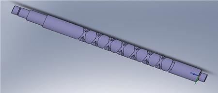

Discussion on the way of closed two-way return thread advance and retreat
   Source of problem
A screw-type part produced by our company is a key component in the transmission mechanism of aerospace products. The material of the part is 2Cr13 stainless steel. There are two spiral grooves on the outer cylindrical surface of the part that are connected end to end and rotate one by one (see Figure 1). ). The technical difficulties in processing are as follows: 1 the left and right spiral grooves of the part are in the middle of the outer circle of the part, the end point of the right-handed spiral groove is the starting point of the left-handed spiral groove, and the end point of the left-handed spiral groove is the starting point of the right-handed spiral groove, two spirals The slots are connected end to end, there is no space for feeding and retracting. If the processing method is not suitable, the two ends of the thread will be damaged. 2 The left and right spiral cavities of the part are trapezoidal, which will make the tool wear faster when machining. The angle of the left and right spiral groove is guaranteed by the side angle of the tool, and it is not good to control whether the tool is vertical when installing the tool. For the parts to be machined, it is easy to cause the spiral groove type to be incorrect.
Figure 1 Schematic diagram of the part body
2. Comparison and practice of processing methods
The G32 of the FANUC system and the G33 of the Siemens system are single thread cutting commands. It requires multiple blocks to complete a thread cutting cycle, and each tool retraction requires separate programming. There are many steps and it is troublesome to use. However, for some special thread cutting, it shows the superiority of its cutting characteristics, and the use of G92, G76 and other cycle commands, but can not produce satisfactory results. The left and right spiral grooves of the part are in the middle of the outer circle of the part, the end point of the right-handed spiral groove is the starting point of the left-handed spiral groove, and the end point of the left-handed spiral groove is the starting point of the right-handed spiral groove, which is connected end to end, and there is no need for the CNC lathe to machine the thread. Knife distance and retraction distance. If threaded fixed cycle is used, the machining quality of such parts cannot be guaranteed. Compared with the above thread turning instructions, the thread of the Siemens system G33 with constant pitch cutting thread is selected.
(1) Advance and retraction mode and path (see Figure 2). Firstly, the G33 turning taper thread method, from point A turning to point B, without returning the knife, and then directly turning to the point C with G33 turning straight thread, without returning the knife, returning directly in the opposite direction, turning the straight thread with G33 Method Turn to D point, or do not need to return the knife, use G33 to turn the straight thread to the E point, then use the G33 turning taper thread to turn from point E to point F, then quickly return to point A, execute the next paragraph program. A-B (taper thread cutting), B-C (straight thread cutting), C-D (straight thread cutting), D-E (straight thread cutting), E-F (taper thread cutting), F-A (fast mobile). The end point coordinate of the X-axis of each thread cutting is the starting point coordinate of the X-axis of the next thread cutting, and the coordinate of the X-axis of point F is the coordinate of the X direction returning to the safety point. The end point coordinates of the final thread are controlled by the coordinates of the X axis of point B.
Figure 2 Path of the knife
When processing the part, the macro program fitting method is used to process. The fitting method is to process the special-shaped thread by continuously changing the starting position of the tool to process the thread, and approaching the actual thread contour point by point. The specific idea of ​​the preparation is as follows: the tooth height is used as a variable to control the radial feed, the tooth profile width at the corresponding radius is determined by calculation, and the tooth width parameter is taken as the axial feed variable, and the cutting edge width is subtracted from the feed. The increment is the axial feed increment to control the axial feed.
(2) Preparation of processing procedures:
M3 S500 (spindle rotation 500r/min)
T1 D1 (No. 1 tool No. 1 tool)
M8 (open cutting fluid)
R1=3.5 (set parameter tooth height 3.5mm)
R2=8.13 (angle 8.13°)
R3=17 (diameter of the base)
AA: R4=R1*TAN(R2) (calculation of the size of the knife)
R5=R3+2*R1 (infeed size calculation)
G0 X30 Z10 (quick positioning)
G33 X=R5 Z-50K22 (taper thread feed)
G33 Z-200 K22 (processing right-handed spiral)
G33 Z-20 K22 (processing left-handed spiral)
G33 Z-100 K22 (turned off the high point left by the taper thread)
G33 X30 Z-150 K22 (cone thread retracting)
G0 Z10 (return)
Z=10-R3-0.5 (tooth left to the left)
G33 X=R5 Z-50K22 (taper thread feed)
G33 Z-200 K22 (processing right-handed spiral)
G33 Z-20 K22 (processing left-handed spiral)
G33 Z-100 K22 (turned off the high point left by the taper thread)
G33 X30 Z-150 K22 (cone thread retracting)
G0 Z10 (return)
Z=10+R3+0.5 (tooth the knife to the right)
G33 X=R5 Z-50 K22 (taper thread feed)
G33 Z-200 K22 (processing right-handed spiral)
G33 Z-20 K22 (processing left-handed spiral)
G33 Z-100 K22 (turned off the high point left by the taper thread)
G33 X30 Z-150 K22 (cone thread retracting)
G0 Z10 (return)
R1=R1-0.1 (infeed depth per layer)
IF (R1<=0) GOTOF BB (conditional judgment)
GOTOB AA (unconditionally returned to the AA block)
BB: G0 X100 (return to a safe location)
M30 (end of program)
references:
[1] Lu Hongxun, Gao Junbo, Qin Lei. Selected textbooks for CNC machining technology [M]. Luoyang: AVIC Air-to-Air Missile Research Institute Press, 2009.
[2] Zhao Yugang, Song Xianchun. Numerical Control Technology [M]. Beijing: Mechanical Industry Press, 2011.