This paper briefly describes the composition principle of the electrical fire monitoring system, and analyzes the design basis and related specifications of the electrical fire monitoring system in the application. Finally, through the introduction of Ankerui residual current electric fire monitoring system in the Qingpu Reeducation Bureau special patient isolation zone project, the realization of the function of the electrical fire monitoring system and its significance are expounded.
High Temperature Alloy is divided into three kinds of material: 760 ℃ high-temperature material, 1200℃ high temperature and 1500 ℃ high temperature materials, the tensile strength is 800 mpa. On other words,it refers to the metal material worked well in the condition of 760-1500 ℃ or above. It owns excellent high temperature strength, good resistance to oxidation and thermal corrosion resistance, good fatigue properties, fracture toughness and other comprehensive performance, this kind of material has became an irreplaceable key material in military and civilian gas turbine engine hot end components . According to the relevant theory, 760 ℃ high-temperature materials, according to the matrix elements,can be mainly divided into high temperature iron base alloy, nickel base superalloy and cobalt-based super alloy. According to the preparation process,it can be divided into deformation and high temperature alloy, casting high temperature alloy and powder metallurgy super alloy. According to the solid methods,it can be divided into solid solution strengthening, precipitation strengthening and oxide dispersion strengthened with fiber reinforced type, etc.
Yang Junjun An Kerui Electric Co., Ltd. Shanghai Jiading
0 Overview
The Qingpu Reeducation Bureau special patient isolation area is located in Qingdong Farm, Qingpu District, Shanghai. The project undertakes part of the electrical fire system on the floor. The Qingpu Reeducation Bureau special patient isolation area has 18 ARCM300-J1 residual current fire detectors installed on the floor. Inside the electric box. The on-site fire detector is connected to the Acrel-6000/B wall-mounted electrical fire monitoring system of the control center by bus. The system has the advantages of convenient installation and transportation, high cost performance and convenient maintenance.
1 reference standard
In recent years, in order to increase the intensity of electrical fire monitoring and prevention, the state has successively formulated or revised a number of relevant standards and regulations to strengthen the prevention of electrical fires. There are:
(1). It is GB50045-95 (2005 edition) "Code for Fire Protection Design of High-rise Civil Buildings", which stipulates in Article 9.5.1 that it is necessary to install a leakage fire alarm system in places with high fire risk and dense personnel in high-rise buildings.
(2). It is GB50016-2006 "Code for Fire Protection of Building Design", which is stipulated in Article 11.2.7: The following places should be equipped with residual current action electrical fire monitoring system. These venues include various types of theaters, galleries, warehouses, residential communities, hospitals, shops, schools, and more.
(3). The relevant provisions of the national standard "Building electrical fire prevention requirements and testing methods" also clearly require that "the residual current action protector that automatically cuts off the power or alarm should be set at the power incoming end".
(4). The products of the electrical fire monitoring system shall meet: GB14287.1-2005 "Electrical Fire Monitoring Equipment", GB14287.2-2005 "Residual Current Electric Fire Monitoring Detector", GB14287.3-2005 "Measurement Temperature Electric Fire Monitoring and Detection" 》
(5). The installation and operation of the electrical fire monitoring system shall meet the requirements of GB13955-2005 "Installation and operation of residual current action protection device"
(6). The power supply of the electrical fire monitoring system shall meet the requirements of GB50052 "Design Specifications for Power Supply and Distribution Systems"
(7). The design of the electrical fire monitoring system shall meet the requirements of the Design Method of Electrical Fire Monitoring System (Interim Provisions)
2 system components
According to the national standard GB14287-2005 "Electrical fire monitoring system" and related specifications "Electrical fire monitoring system design method" (interim regulations), the basic components of the electrical fire monitoring system should include: electrical fire monitoring equipment, residual current electrical fire It consists of three basic product categories: monitoring detectors and temperature-measuring electrical fire monitoring detectors.
The residual current type electrical fire monitoring system adopts a layered distributed structure, which is composed of a station control layer, a network communication layer and a field device layer. Each electrical fire monitoring detector accesses the communication server through the shielded twisted pair RS485 interface, adopts the MODBUS communication protocol bus type connection, and then enters the industrial switch through the Category 5 TCP/TP protocol, and then reaches the monitoring host through the optical cable.
System networking structure 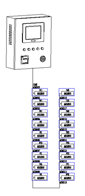
1) Station management
The management of the station control management system for the electrical fire monitoring system is the direct window of human-computer interaction and the uppermost part of the system. Mainly composed of system software and necessary hardware equipment, such as touch screen, UPS power supply and so on. The monitoring system software calculates, analyzes, and processes various types of data information on the site, and responds to the on-site transportation situation by means of graphics, digital display, sound, and indicator lights.
Monitoring host: used for data collection, processing, and data forwarding. Provides data interfaces for system management, maintenance, and analysis within and outside the system.
UPS: Ensure the normal power supply of the computer monitoring system, and ensure the normal operation of the station management management equipment when the whole system has power supply problems.
The background monitoring device is set in the control center.
2) Network communication layer
Communication medium: The system mainly adopts shielded twisted pair cable, realizes real-time communication between field device and host computer by RS485 interface and MODBUS communication protocol.
3) Field device layer
The field device layer is a data acquisition terminal, mainly for the ARCM300-J1 residual electrical fire monitoring detector. The ARCM300 residual current electrical fire monitoring detector is designed for TT and TN systems below 0.4kV. It monitors and manages fire risk parameters such as residual current, conductor temperature, overcurrent and overvoltage in the distribution circuit. Thereby preventing the occurrence of electrical fires. The product adopts advanced microcontroller technology, with high integration, small size, convenient installation, intelligent, digital and networked. It is an ideal choice for building electrical fire prevention monitoring and system insulation aging prediction. The product complies with the standard requirements of GB14287.2-2005 "Electrical Fire Monitoring System Part 2: Residual Current Electrical Fire Monitoring Detector".
The distributed I/O controller connected to the fieldbus constitutes a data collection terminal and uploads the collected data to the data center. The measurement detector is responsible for the most basic data acquisition tasks, and the monitored data must be transmitted to the monitoring host in complete, accurate and real-time. It is convenient for the operating personnel to monitor the running status of the field equipment, fault alarms, etc., to effectively prevent fire accidents.
3 system characteristics and working principle
The characteristic of the electrical fire monitoring system is that the residual current electrical monitoring is an advanced pre-alarm system. Unlike the traditional automatic fire alarm system, the early warning of the electrical fire monitoring system is to avoid losses, while the traditional automatic fire alarm system is to reduce losses. Therefore, this means that whether it is a new or rebuilt project, especially the unit that has installed the automatic fire alarm system, the root cause of the electrical fire monitoring system still needs to be installed.
The electrical fire monitoring system measures two physical quantities of residual current and temperature.
The residual current measurement is based on Kirchhoff's current law: at the same time, the sum of the current vectors flowing into and out of a node in the circuit is zero. Taking the TN-S system as an example, A/B/C/N is simultaneously passed through the residual current transformer. When there is no leakage in the system, the current vector sum of the residual current transformer flowing into and out is zero. At this time, the residual current The secondary current induced by the transformer is also 0; when a relatively large earth leakage occurs, the current vector sum of the current transformer flowing into and out of the residual current is no longer zero, and its magnitude is equal to the current flowing from the earth, that is, the leakage current. The leakage signal is transmitted to the electrical fire detector through the secondary wiring of the residual current transformer, and is sent to the CPU after operation amplification, A/D conversion, and after a series of algorithms, the amplitude of the change is analyzed and judged, and The alarm set value is compared. If the set value is exceeded, an audible and visual alarm signal is sent and sent to the background electrical fire monitoring device.
The temperature measurement uses a temperature sensor, which is generally measured using a Pt100 sensor. This type of temperature sensor is stable in temperature measurement and has a wide measuring range. It is suitable for monitoring cable temperature and ambient temperature in the field. When the temperature changes, the resistance value of Pt100 changes in the same proportion. The resistance signal is transmitted to the electrical fire detector. After a series of signal conversion and calculation, the final result is compared with the temperature alarm setting. If the value exceeds the fixed value. An audible and visual alarm signal is sent and sent to the background electrical fire monitoring device.
4 System parameter configuration
4.1 Alarm value setting range
According to the national standard GB14287.2-2005, the alarm value of the residual current type electrical fire monitoring detector is set between 20~1000mA. According to this requirement, the residual current action value at the power supply main line is generally set to 400~800mA, and the residual current action value on the power branch line is set to 100~400mA. Generally, the residual current type electrical fire monitoring detection is set at the actual site. The alarm value of the device shall not be less than 2 times the maximum value of the leakage current during normal operation of the protected electrical circuit and equipment, and not more than 1000 mA. The alarm setting value of the electrical fire detector should take into account the normal leakage current of the power distribution system and the electrical equipment.
4.2 Refer to the cable temperature rise alarm setting reference, according to the "Power Cable Design Specification" for the cable temperature requirements
(1) High temperature places above 60 °C should be selected according to the requirements of high temperature, duration and insulation type. Heat-resistant PVC, XLPE or Ethylene-propylene rubber insulation and other heat-resistant cables should be used. Insulated cable. It is not advisable to use ordinary PVC insulated cables in high temperature places.
(2) The ambient temperature of the cable's continuous allowable current carrying capacity shall be determined according to the multi-year average of the meteorological temperature of the area of ​​use and shall comply with the regulations. When the indoor cable trench is laid, the ambient temperature is the average daily maximum temperature of the hottest month of the site plus 5 °C.
(3) The temperature rise of the cable is related to the laying and heat dissipation conditions.
5 System Introduction
The Acrel-6000 electrical fire monitoring system is an industrial grade that is independently developed by the company to receive field devices such as residual current electrical fire detectors to achieve alarm, monitoring, control, and management of protected electrical circuits. Hardware/software system. The system is applied to the fire control center of large shopping malls, living quarters, production bases, office buildings, shopping malls and other areas, and telemetry, remote adjustment, remote control and remote signaling of detectors scattered in the building are convenient for monitoring and management. The system uses a standard Modbus field bus to connect detectors with communication functions. When the detected parameter in the field protection circuit exceeds the alarm set value, it can send out alarm signals and control signals, can indicate the alarm part and save the alarm. information.
The main technical parameters 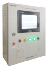
(1). Power supply:
1 rated working voltage AC220V (-15% ~ +10%)
2 Backup power supply: When the main power supply is under voltage or power failure, maintain the monitoring equipment working time ≥ 4 hours
(2). Work system:
24-hour work schedule
(3). Communication method:
RS485 bus communication, Modbus-RTU communication protocol, transmission distance 1km, can extend communication transmission distance through repeater
(4). Monitoring capacity:
1 Monitoring equipment can monitor up to 200 monitoring units (detectors)
2 can be connected with ARCM series monitoring detector
(5). Monitoring alarm items:
1 Residual current fault (leakage): fault unit attribute (part, type)
2 Temperature alarm (over temperature): Fault unit attribute (part, type)
3 Current fault (overcurrent): Fault unit attribute (part, type)
Monitoring alarm response time: ≤30s
Monitoring alarm sound pressure level (A weighting): ≥70dB/1m
Monitoring alarm light display: red LED indicator, red light alarm signal should be maintained until manual reset
Monitoring alarm sound signal: can be manually eliminated, can be started again when there is alarm signal input again
(6). Fault alarm item:
1 The communication cable between the monitoring device and the detector is open or shorted.
2 Monitoring equipment main power supply undervoltage or power failure
3 The cable between the charger that charges the battery and the battery is broken or shorted.
Fault alarm response time: ≤100s
Monitoring alarm sound pressure level (A weighting): ≥70dB/1m
Monitoring alarm light display: yellow LED indicator, yellow light alarm signal should be kept until troubleshooting
Fault alarm sound signal: can be manually eliminated, can be started again when there is an alarm signal input again
The normal operation of the non-faulty loop is not affected during the fault
(7). Control output:
Alarm control output: 1 set of normally open passive contacts, capacity: AC250V 3A or DC30V 3A
(8). Self-test items:
1 Indicator check: alarm, fault, operation, main power, standby power indicator
2 display check
3 audio device inspection
Self-test time ≤60s
(9). Event record:
1 Record content: record type, time of occurrence, detector number, area, fault description, can store no less than 20,000 records
2 record query: query according to the date, type and other conditions of the record
(10). Operational rating:
1 Daily duty class: real-time status monitoring, event record query
2 Monitoring operation level: real-time status monitoring, event record query, detector remote reset, device self-test
3 System management level: real-time status monitoring, event record query, detector remote reset, device self-test, monitoring device system parameter query, monitoring device module detection, operator addition and deletion
(11). Environmental conditions for use:
1 Workplace: Fire control room, manned substation (distribution room), wall on room where someone is on duty
2 Working environment temperature: 0 ° C ~ 40 ° C
3 Working environment relative humidity: 5% ~ 95% RH
4 Altitude: ≤2500m
basic skills
(1). Monitoring alarm function:
The monitoring equipment can receive the leakage and temperature information of multiple detectors, and emit an audible and visual alarm signal when the alarm occurs. At the same time, the red “alarm†indicator on the device lights up, the display indicates the alarm location and alarm type, and the alarm time is recorded. The sound and light alarm is always maintained. Until the display is reset by pressing the display "Reset" button. The audible alarm signal can also be manually removed using the display "Muffler" button.
(2). Fault alarm function:
Communication failure alarm: When a communication failure occurs between the monitoring device and any of the connected detectors, the corresponding detector in the monitoring screen displays a fault indication, and the yellow “fault†indicator on the device lights up, and a fault alarm sound is emitted. .
Power failure alarm: When the main power or backup power fails, the monitoring device also emits an audible and visual alarm signal and displays the fault information. You can enter the corresponding interface to view the detailed information and release the alarm sound. Hardware Business Network Information Center)http://news.chinawj.com.cn
High Temperature Alloy
High Temperature Alloy,High Temperature Alloy Wire,High Temperature Alloy Anti-Corrosion ,High Temperature Tooling Tungsten Alloy
Jiangsu nickel alloy Co.,Ltd , https://www.xhalloy.com