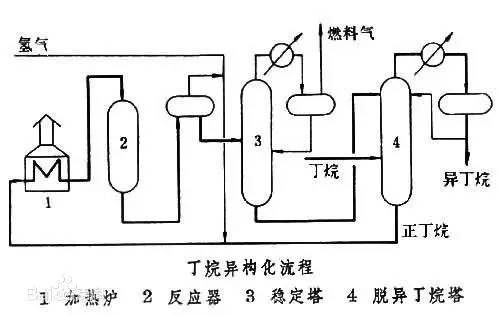
◆  ◆  ◆ Isomerization device flow chart The isomerization unit is similar to a conventional hydrotreating unit. Taking butane isomerization as an example (see figure), the butane feed is separated from isobutane by a deisobutane column. The bottom of the column is mainly n-butane, mixed with hydrogen and heated into the reactor. The reaction pressure is about 2.1 to 2.8 MPa, the temperature is 145 to 205 ° C, the hydrogen to hydrocarbon molar ratio is 0.1 to 0.5, and the space velocity is 3 to 5 h-1. The reaction product is separated by hydrogen (recycled) through a separator, and a small amount of cracked gas (used as a fuel gas) is separated by a stabilizing column to remove the isobutane column. The bottom of the column is n-butane cycle reaction, the yield of isobutane can reach more than 90%. When isobutane is used as an alkylation replenishment feed, the unit can be combined with an alkylation unit into a single unit, which saves equipment and investment. ◆  ◆  ◆ Benzene extraction device flow chart The benzene extraction device is used as a device for extracting benzene contained in reformed gasoline, and mainly includes the following parts: pre-fractionation, extraction distillation, solvent recovery and regeneration, benzene refining, and C6 non-aromatic hydrogenation reaction, fractionation. ◆  ◆  ◆ Partial flow chart of diesel hydrogenation reaction The raw material oil from the tank area is controlled by the liquid level and flow rate of the raw material oil buffer tank, and the raw material oil filter removes the particles larger than 25 micrometers in the raw material, and then enters the raw material oil buffer tank, and the raw material oil buffer tank is sealed with the fuel gas. . The feedstock oil from the feedstock buffer tank is pressurized by the hydrogenation feed pump, and after being exchanged by the reaction effluent/feedstock oil heat exchanger under flow control, mixed with mixed hydrogen to enter the reaction effluent/reaction feed. The heat exchanger is then heated to the desired temperature of the reaction via a reaction feed furnace and into the hydrofinishing reactor. The reactor is provided with two catalyst beds with an injection cold hydrogen facility between the beds. The reaction effluent from the hydrofining reactor is passed through the reaction effluent/reaction feed heat exchanger, the reaction effluent/low-oil heat exchanger, the reaction effluent/feedstock oil heat exchanger in sequence with the reaction feed, low The oil is separated and the raw material oil is exchanged, and then cooled to 45 ° C through the reaction effluent air cooler and water cooler, and enters the high pressure separator. In order to prevent the ammonium salt in the reaction effluent from being precipitated at a low temperature portion, the deoxidized water is injected into the pipe on the upstream side of the reaction effluent air cooler by a water injection pump. The cooled reaction effluent is subjected to three-phase separation of oil, gas and water in a high pressure separator. After the high-gas (recycled hydrogen) is separated by the circulating hydrogen compressor inlet liquid separation tank, it enters the circulating hydrogen compressor to be boosted, and then splits into two channels: one as the quenching hydrogen into the reactor; one way and the new from the new hydrogen compressor Hydrogen is mixed and mixed hydrogen is mixed with the feedstock oil as a reaction feed. The sulfur-containing and ammonia-containing sewage is discharged from the bottom of the high-pressure separator to the acidic water stripping device for treatment. The high-separation oil phase enters the low-pressure separator through the pressure-reducing regulating valve under the control of the liquid level, and the flash gas is discharged to the factory fuel gas pipe network. The low-oil-reduced refined diesel/low-oil heat exchanger and the reaction effluent/low-oil heat exchanger respectively exchange heat with the refined diesel and the reaction effluent and enter the diesel stripper. The inlet temperature is controlled by the reaction effluent/low oil separator heat exchanger bypass. The new hydrogen enters the new hydrogen compressor through the liquid separation tank of the new hydrogen compressor inlet, and is mixed with the circulating hydrogen after being boosted by two stages. ◆  ◆  ◆ Diesel hydrogenation fractionation flow chart The low oil fraction from the reaction part is exchanged to the diesel stripper by heat exchange to the refined diesel/low oil heat exchanger and the reaction effluent/low oil heat exchanger to about 275 °C. The bottom of the tower is stripped with 1.0MPa superheated steam, and the top of the tower is condensed and cooled to 40 °C by the stripper at the top of the stripper and the top of the stripper, and then enters the reflux tank at the top of the stripper for gas, oil and water separation. . The flashed gas is discharged to the catalytic device. The oil phase is boosted by the reflux pump at the top of the stripping column as part of the reflux of the column, and a part is used as a crude gasoline decatalytic device. The sulfur-containing ammonia-containing sewage is sent out to the device together with the high-stakes sewage. In order to suppress the corrosion of hydrogen sulfide on the overhead pipe and the cold-exchange equipment, a corrosion inhibitor is injected in the top pipe. The corrosion inhibitor is injected into the tower top pipe from the corrosion inhibitor tank through the corrosion inhibitor pump. The refined diesel oil at the bottom of the tower is pressurized by the diesel pump and exchanges heat with the low oil to about 80 °C, and then enters the diesel air cooler and cools to 50 °C. ◆  ◆  ◆ Flow chart of steam coal hydrogenation reaction ◆  ◆  ◆ Flow chart of hydrogenation fractionation of aviation coal ◆  ◆  ◆ Hydrogen production unit flow chart ◆  ◆  ◆ Hydrogen steam making part process diagram ◆  ◆  ◆ Sulfur recovery sulfur part flow chart ◆  ◆  ◆ Sulfur recovery tail gas flow chart ◆  ◆  ◆ Solvent regeneration device flow chart ◆  ◆  ◆ Acid water stripper process ◆  ◆  ◆ PP device reaction part flow chart In the petrochemical industry, PP equipment refers to a polypropylene production unit mainly used for the polymerization of propylene to produce polypropylene. The reaction portion includes a first polymerization reaction unit and a second polymerization reaction unit. The first polymerization reaction unit refers to a horizontal stirred bed reactor under a certain temperature and pressure, using propylene as a main raw material, using hydrogen as a relative molecular mass regulator, and reacting under a catalyst system to form a polypropylene by gas phase reaction polymerization. Powder. The second polymerization reaction unit setting and control method is basically the same as that of the first polymerization reaction unit, and the purpose is to improve the utilization efficiency of the catalyst, and at the same time, by using the series connection characteristics of the second polymerization reaction unit and the first polymerization reaction unit, ethylene is added to produce impact copolymerization. Object. ◆  ◆  ◆ PP device flashing, steaming part of the flow chart ◆  ◆  ◆ PP device granulation part flow chart The polypropylene resin is mixed with different types of additives, heated at a high temperature (200 € 300 ° C) to reach a molten state, and subjected to underwater granulation by a template under the action of a twin-screw extruder and a molten gear pump. The main purposes of granulation are: Add various additives to improve product performance; Facilitate product packaging and transportation; improve product quality. ◆  ◆  ◆ Storage and transportation system device, tank area oil system pipeline flushing principle flow chart ◆  ◆  ◆ Storage and transportation venting system flow chart ◆  ◆  ◆ Air separation system flow chart The air separation unit is a set of industrial equipment used to separate the components of the air to produce oxygen and nitrogen. Briefly, in general, an air separation unit refers to a separation device for various air components in a chemical plant. Specifically, gases such as nitrogen, oxygen, and argon, and other gases are separated from the air. ◆  ◆  ◆ Chemical water flow chart ◆  ◆  ◆ Circulating water field flow chart The circulating water is pressurized by the circulating water pump and outputted. Most of the water is exchanged in the water workshop. The return water of the heat exchange enters the pool after being cooled by the cooling tower, and some of them are filtered through the valveless filter and returned to the pool. When the circulating water index is close to the high limit, the sewage pump is turned on for replacement, and the circulating pool is replenished. ◆  ◆  ◆ Salt water treatment flow chart ◆  ◆  ◆ Oily sewage treatment flow chart The Disposable Paper Face Mask is comfortable to wear, and using a low impedance filter material with no odor, white elastic ear loop. Non-woven fabric and paper material allows for comfortable breathing. Adjustable metal strip ensures optimal sealing between the bridge of the nose and the mask. The price of Face Mask is very good which can meet your demand. Disposable Paper Face Mask Disposable Paper Face Mask,Disposable Paper Towel Face Mask,Disposable Paper Face Mask N95,Disposable Face Mask Shandong Shengquan New Materials Co., Ltd. , https://www.sqnewmaterials.com


Chemical equipment flow chart