Stearyl Erucamide,Octadecyl Erucamide Cas 10094-45-8,Cas 10094-45-8,Octadecyl Erucamide Jiangxi Zhilian Plastics & Chemicals Technology Co., Ltd , https://www.zhilian163.com
figure 1 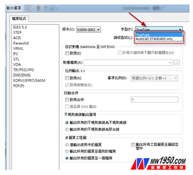
figure 2 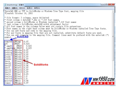
image 3 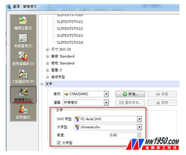
Figure 4 
Figure 5 
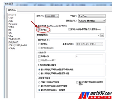
Figure 7 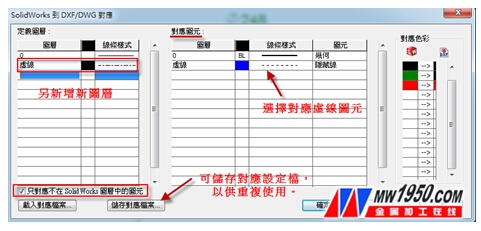
Figure 8 
Figure 9
SolidWorks drawing output setting summary
Output DWG file, how to correctly set Chinese characters
In the era of product model development, the trend of 3D construction has gradually been gradually reduced, which can reduce the labor cost of the product in the development process, and does not require repeated trials in the later stage of product development. In the environment of 3D construction, product design and inspection can be carried out more intuitively to achieve product development and optimization design. However, there are still many companies or processing plants in the industry that use 2D drawings to communicate. Therefore, we often provide the files associated with the other party's files for the communication of file transmission, and output them in the 2D drawing DWG and DXF file formats.
When you export a drawing to a DXF or DWG file in SolidWorks, the view in the file will apply the drawing page scale of the drawing. All pixels in the layer (such as edges, annotations, and assembly components) are also output to the specified layer. However, if you have encountered SolidWorks output into DXG/DXF files, but the problem of font display garbled and trouble you a lot? ? In the end, how to set up to avoid garbled? ?
In fact, this problem is not difficult! ! ! As long as you learn more about the differences in font databases used between SolidWorks and DraftSight (eg AutoCAD), the problem of garbled fonts can be solved! ! Since the font library resource of the SolidWorks software itself is from the font database (TrueType font) inside Windows, the fonts in Windows can be opened for the user's needs, as shown in Fig. 1. Or for the font setting, cancel the option to hide the font according to the language setting, and open the display of all the fonts in Windows to be applied in SolidWorks.
However, the fonts read in DraftSight or AutoCAD are from the font database (AutoCADSHX font) that the software itself has. Therefore, after using the font of Windows, it can be displayed normally in DraftSight or AutoCAD. Therefore, when SolidWorks outputs the drawing file, you can choose to use the fonts TrueType & AutoCAD Standardonly, as shown in Figure 2. At this time, we can choose to output the appropriate AutoCAD version, line type, layer, scale and map page, etc. according to the user's needs.
What is TrueType Font & AutoCADSHX Font? ?
The following will explain in detail to you:
First, TrueType fonts: Usually, users commonly use the "detailed body" and "standard body" in the DWG image file. The advantages of TrueType fonts can display "English/Digital/Chinese" at the same time. Disadvantages, if a large amount of data is used in the drawing, it will cause slow delays in opening and reshaping. When you use special TrueType fonts (such as: Huakang blackbody, full-true round body and other fonts), if you don't have these special fonts on other user computers, the system will automatically replace the default fonts.
Second, SHX font: The user commonly used in the DWG image file according to the default "txt font" and "chineset large font" two ways. Txt (font file) is mainly used to display "English/number", Chinesee (large font file) is used to display "Traditional Chinese", and general "text type" is used with "SHX font" and "SHX large font" combination. Effectively reduce resource consumption, and there will be no delays in opening and reshaping.
Therefore, in order to present the same font display in the 2D image file, SolidWorks generally recommends selecting the TrueType font output when outputting the DXF/DWG file, which can be solved for most Chinese character garbled characters. Compared with when you output in SolidWorks, you choose to output in AutoCADStandardonly font mode, which uses the default corresponding font file drawFontMap.txt to correspond to the font, as shown in Figure 3.
The corresponding font file location is drawFontMap.txt in the C:\ProgramFiles\SolidWorksCorp\SolidWorks\data folder path. As shown in Figure 3, in the default corresponding file, the left column lists the AutoCADSHX or TrueType fonts from the source drawing. The right column lists the fonts used by SolidWorks or Windows TrueType when AutoCAD drawing text is mapped to a new SolidWorks drawing. Therefore, when you save SolidWorks files as DXF or DWG files, you can use the drawFontMap.txt file to map any SolidWorks or Windows TrueType fonts back to AutoCADSHX or TrueType fonts. When you open a drawing file in DraftSight, the correct font is used and there is no need to replace the default font. Therefore, this can improve the correctness of the display of the drawing file.
On the contrary, the "txt font" and "chineset large font" can also be used under the interface of DraftSight to solve the problem of Chinese character garbled, as shown in Figure 4. Therefore, whether in the process of outputting files in SolidWorks or entering files in DraftSight environment, as long as you fully understand the correspondence between fonts in software or replace txt fonts and Chinese fonts, you can successfully solve Chinese. The problem of garbled characters.
Layer correspondence and setting
The use of 3D construction models is a very intuitive and fast method in both the design process and model validation. However, when the 3D file needs to be output as a 2D image file, in order to understand the structure of the model design structure more clearly, the layer will be used for management and display. Next, I will use a simple example to explain to you:
First, in the SolidWorks drawing, we can create a layer for the display of the model outline for the requirements setting, as shown in Figure 5. Here we can add a new dimension (green) and centerline label (red) layer settings, you can also set the line type and thickness.
Once the layer settings have been made, the layers are applied directly to the dimensions and centerline symbols noted in the drawing. You can apply a predefined layer in the Attribute Manager --> Other Options, as shown in Figure 6.
Image 6
Usually, when a SolidWorks drawing is used with a predefined layer, it can be immediately output to the DXF/DWG file format for use. However, in order to ensure that SolidWorks is output to DXF/DWG format, its layer corresponds to the association. You can also select the Enable SolidWorks to DXF/DWG enable option by clicking the --> option while selecting the output file type, as shown in Figure 7. In this way, the relationship corresponding to the file output layer can be further set.
After the point is selected from the definition corresponding to SolidWorks to DXF/DWG startup determination, a window corresponding to SolidWorks to DXF/DWG will appear. At this point, we can set according to the required layer pixel correspondence, as shown in Figure 8. The following is a description of each field function:
1. Define the layer
=> will display the corresponding layer. You can add, edit, or delete layers. Select a color and line style from the list. Layers and DEFPOINTS are fixed layers and cannot be deleted. The {DEFPOINTS layer is in the AutoCAD drawing}.
2. Corresponding pixels
=> will display the corresponding pixel. You can add, edit, or delete pixels. Select a color, line style, and pixels from the list. If you don't specify a color or line style, BYLAYER will appear, meaning that the pixel's color and line style are the same as the layer's properties.
3. Corresponding color
=> Color correspondence can be used alone or in combination with pixels. The color correspondence definition takes precedence over the pixel corresponding definition.
4. Check only the pixels that are not in the SolidWorks layer.
=> Select to apply the settings of the corresponding file to only the pixels whose layers are not defined, and keep the existing SolidWorks drawing file layer in the output file. If cleared, the definition of the corresponding file will overwrite the current SolidWorks drawing file layer.
5. Load\save the corresponding file
=> After the corresponding layer pixel is matched, the file can be saved or applied in a profitable manner.
After setting the layer parameters, the DXF/DWG format file can be successfully output. At this point, the layer attribute associations in the file are also set together, as shown in Figure 9. From the figure we can clearly see that in addition to the original layer properties have been applied, but we added the new dotted layer pixels are also applied to the file. Therefore, we can quickly add and edit layer pixels through the corresponding way of this layer, and complete the management and display effect of the parts on the 2D surface.